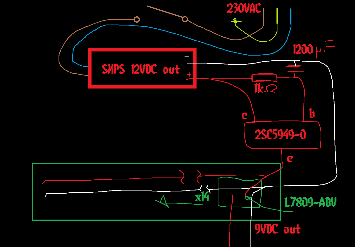
I am trying to filter ~200W of 12VDC through a capacitance “multiplier” and idk if I messed up or I’m just lacking some knowledge. so I have a mystery SMPS putting out 12VDC with 200W headroom, and I’m using a Toshiba 2SC5949-0 BJT NPN transistor over 1200μF electrolytic cap (didn’t pop, I am a genius) and 1KΩ metal oxide resistor. The rail then feeds a bunch of linear regulators to get down to 9VDC, and I hoped I had enough space to get rid of the ripple.
it started self oscillation anyway and took about a minute to settle into just some noise (still annoying this is what I’m trying to get rid of!!!)
any way, if you know what I did wrong, please let me know because I think I did everything perfectly right
I unhooked it for now and I tried it in the old configuration and it made a loud bang in the amp’s speakers so I am just tiptoing around the idea it blew up all my pedals, but it shouldn’t have because the regulators should pop before passing more than 9V I thinkk I hope
thank you
I want to just add, I saw no smoke, burn marks or popped caps, the transistor got REAL warm though
I don’t know anything about hardware, but I asked a friend about this to see if they could help. Here’s what they said:
I’m afraid I don’t really get what they’re doing, or what they’re trying to do. There’s no diagram so I can only try to guess exactly what’s connected where. By the end, I think I can piece together that they are trying to power some 9V guitar pedals? But 200W is a huge amount for some pedals (even the LED displays I made with thousands of LEDs don’t use that much).
I hadn’t heard of a capacitance multiplier, but I see now that it is a thing (I can’t give any advice for that, though). I assume they mean that the ripple is on the 12V side rather than the 9V side, which sounds weird to me, since they’re linear regulators, not switching regulators. They mention “a bunch of” regulators - are they too high-current / too many for the power supply to handle? (They don’t say how many or what the regulator’s part number is)
The capacitance multiplier makes me question whether I have the knowledge to be able to help, but without a diagram and with so much information missing, it’s kinda impossible for me to even begin to try to help.
But the most obvious solution would be to use a power supply that’s 9V to begin with and do away with the 9V regulators, because trying to regulate 200W with linear regulators will make a lot of heat even if it can be done. “Mystery SMPS putting out 12VDC with 200W headroom” makes me think they are using one of these power supplies: https://www.aliexpress.com/item/1005002288446809.html
I’ve used lots of these for projects too, and they are made for many voltages and currents (there’s a 9V 30A = 270W one listed there).
Also, if they have that type of PSU, then there is a potentiometer near the wire connectors that you can turn with a screwdriver to adjust the voltage +/- a little. They might be able to adjust it down to 9V
how silly of me not to include a diagram or other part numbers!!
yes I am using one of the very functional LED strip light drivers! yes it’s a lot of power for one pedal, but it’s to run a whole pedalboard (some of these pedals are almost 12W each!!!)! the linear regulators don’t have enough ripple rejection on their own to block out the noise from the SMPS brick they are the L7809-ABV which is a 9V regulator with a 2V drop. I did do the maths once, and there should be enough power to both filter the 12V and still run the regulators, but I am pretty bad at maths!
I hope this helps in securing an answer if your friend is interested still, or otherwise from the greater community, thank you!
(also the email notification I got had what I can only assume is your name in the title field just if you didn’t know. I know there’s a field for it on this site but if you didn’t know it’s going to add that it does.)
EDIT :: I should also mention that AC Earth and DC GND share a plane, I asked a few electronics people and they said this was fine, it was mostly for safety and not having to isolate mounting hardware on the DC board, this might contribute to the noise with a 60Hz carrier wave, but realistically it shouldn’t unless the AC circuit fails to Earth (which it shouldn’t be doing)